GREEK "PALINTONE" TORSION-POWERED SIEGE CATAPULT
site d'origine : http://www.legionxxiv.org/lrgballistacrew/
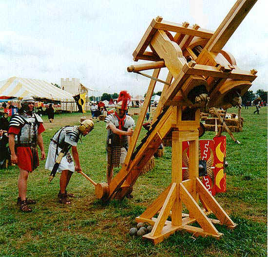
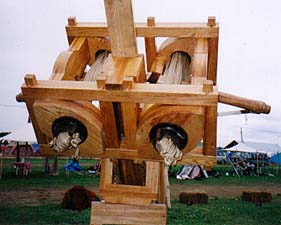
STONE THROWING BALLISTA
A Greek "Palintone" type Ballista Catapult Engine being prepared for firing during PENNSIC WAR XXIX, near New Castle, PA. Darius Architectus (Kurt A. Suleski), the crew commander and builder of the engine, stands at left surveying the "field of fire"; as Gaius Licinius Marcellus (Daniel Collins - center) and Gallio Velius Marsallas (George Metz) operate the winch levers that will "cock" the weapon for discharge. This machine is a meticulously researched, museum quality recreation of a medium size Greek Ballista Siege Catapult and is capable of throwing a three pound concrete ball more than 200 yards! The balls are visible at the base of the machine.
This machine is similar to the ballista siege engines later used by the Romans. The Roman engines differed from the Greek machines in having a rachet wheel and pawl at the capstan winch (carchesium) instead of the long toothed racks on the sides of the ladder beam (scapus climacidos). Also, some of the structural members comprising the torsion head on the Roman engines had a different appearance. The weapon is powered by two horizontal cross-bow like arms, which are inserted into two vertical and tightly wound "skein" springs of braided nylon rope contained in the rectangular frame structure. The Romans used skein springs made from gut or hemp. This replica originally employed gut/hemp skeins; but after some difficulties, braided nylon was substituted. There is no record of the Romans having used metal springs in their torsion powered catapulta.
The original concept and design for this type of catapult came from the Greeks. The smallest stone-throwing torsion "Palitones" catapult engine mentioned by the Greeks threw a stone weighing 10 minae, equal to 9.6 pounds. Such a machine would have been about 16 feet long overall. Practical size limitations for portability dictated that this machine be constructed as a 3/4 size replica about 12 feet long. It is not a toy! . . . But, a powerful weapon requiring skill and prudent care to be operated safely.
More information is available from the builder, Kurt Suleski (Darius Architectus) at Knight's Armoury ksuleski@isd.net
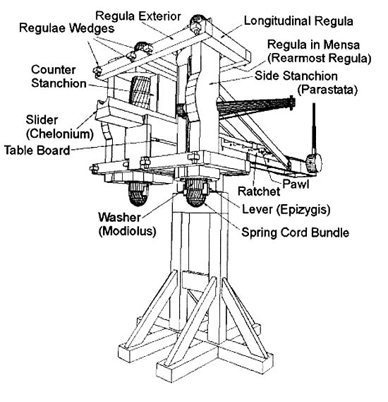
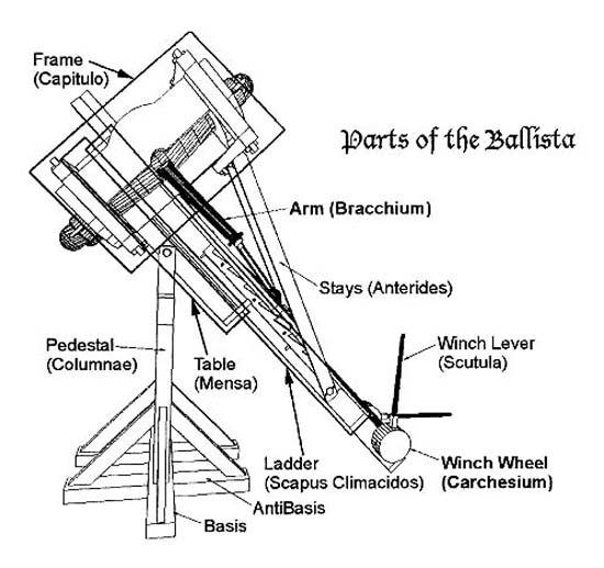
Isometric Plans from "Build Your Own Greek Siege Engine" by Kurt Suleski
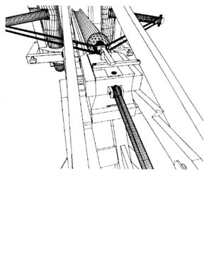
On the left, is a rear isometric view showing the ballista ready for discharge. The launching slide, carrying the trigger release, has been drawn back by the windless. This action has also drawn back the torsion arms, twisting them to the rear, against the resistance of the skeins, thus creating the power to launch the projectile.
On the right, is a close-up isometric view showing the projectile ball in firing position, just in front of the trigger release. This view looks forward along the launching trough that the projectile will follow much like a rifle barrel.
*** S.P.Q.R. *** LEGION XXIV MEDIA ATLANTICA *** S.P.Q.R. ***
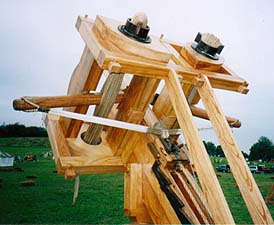
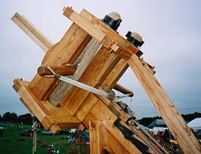
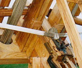
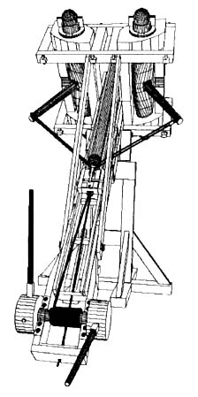
Detail photos of the Ballista. A close-up of the trigger mechanism is at lower right, showing a three pound ball in the launching sling. The the trigger pawl is engaging the sling loop. The trigger is released by yanking the horizontal bar out from under the tail of the trigger pawl. To the left of the trigger is one of two "cocking" pawls; which engages the ratchet bars on either side of the ladder beam; which comprises the "tail" of the machine. The weapon is aimed by lifting the ladder beam and visually pointing it toward the target area.